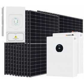
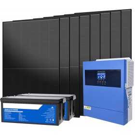
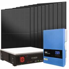
DEYE SE-F5-PRO 6000-9000W Off Grid...
€4,963.20 €8,272.00
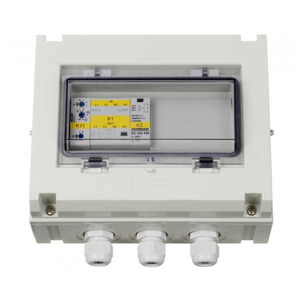

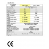

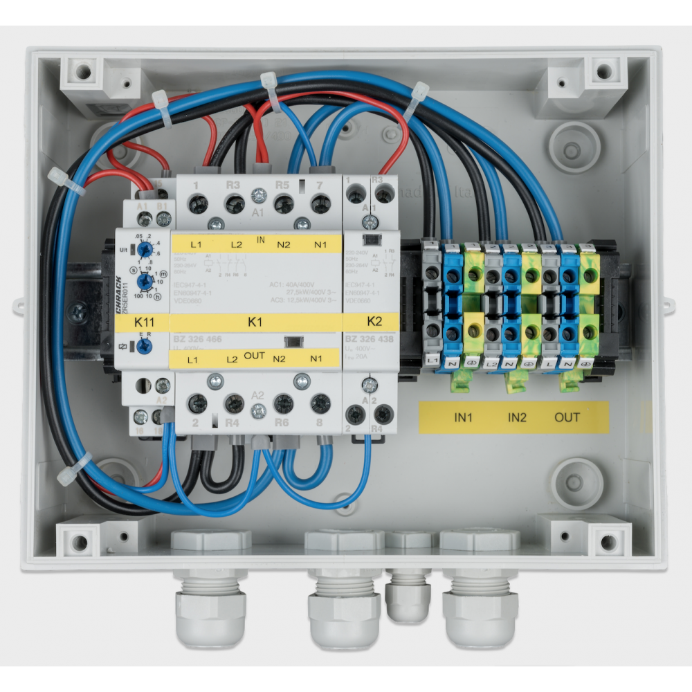
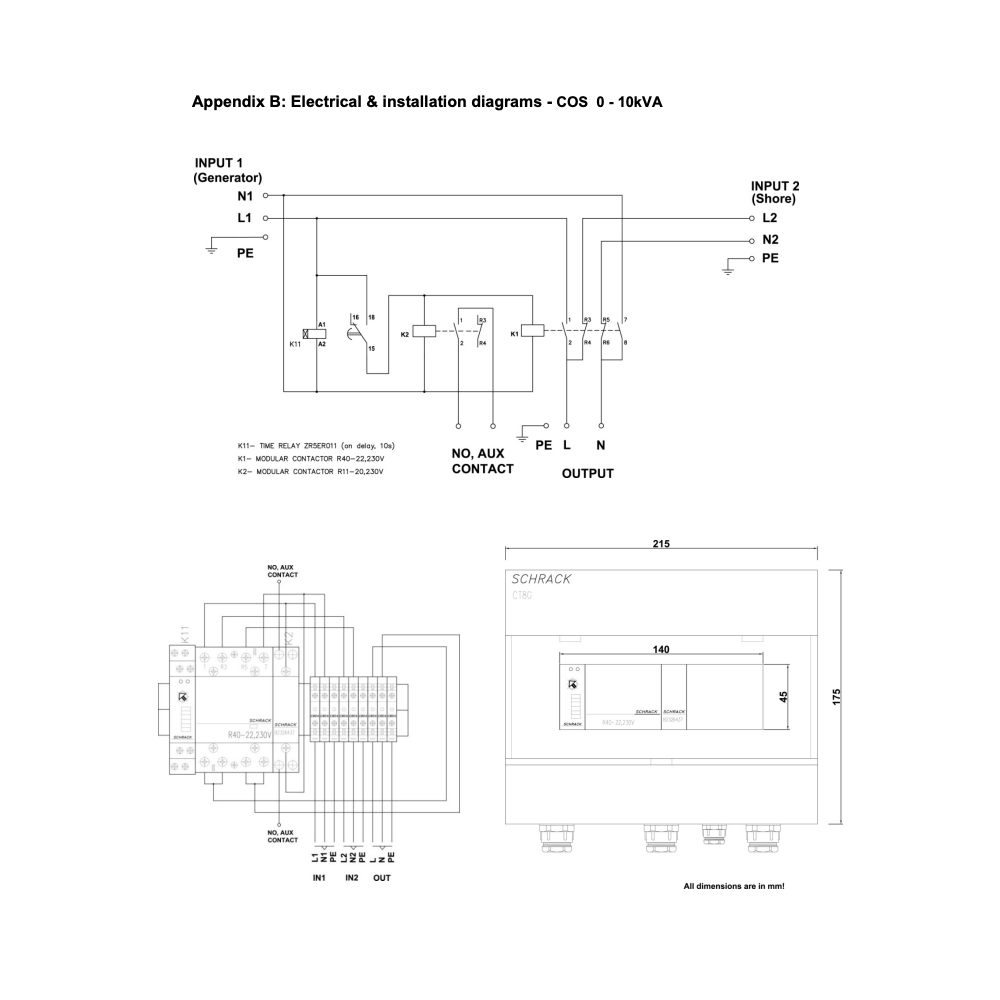
Automatic Transfer Switch Victron Energy 10kVA/230V monofase Mpn: COS230103100
The TRANSFER SWITCH is designed to take over automatic switching between 2 different power sources
The TRANSFER SWITCH is designed to take over automatic switching between 2 different power sources: between a generator
and the shore, or between an inverter and a generator, or between an inverter and the shore. The TRANSFER SWITCH has
two inputs and one output and automatically transfers the available AC power to output. It can be used with any Victron Energy
inverter, depending on the capacity.
Operation
The TRANSFER SWITCH is situated between a generator or shore and inverter. If the voltage level or the frequency of the
generator or the shore varies (input 1), then the TRANSFER SWITCH switches to the inverter (input 2). Once the generator or
the shore supply has remained continuously stable, the TRANSFER SWITCH switches back (input 1) with a delay of
approximately 10 seconds. This way, the appliances are protected against damage from voltage drops. During transfer between
one of the power sources (input 1 or input 2), the appliances are not supplied with power for a short time. Because of this,
computers, electronic devices etc. connected to this group might lose data. The TRANSFER SWITCH can be used with any
type of inverter but the best results, however, are obtained with an inverter from Victron Energy.
1.1 Installation
• WARNING! Be sure that all AC power sources are switched off or disconnected during installation.
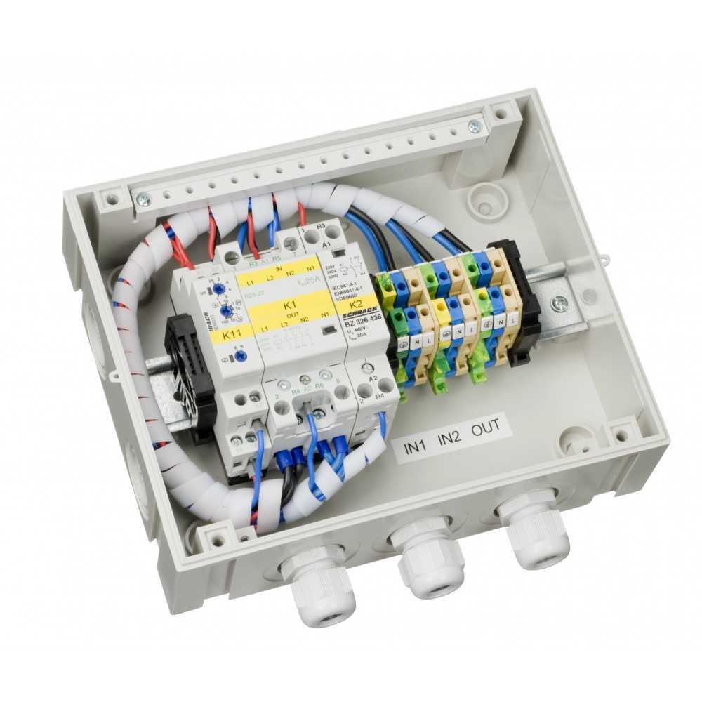
• Install the TRANSFER SWITCH in a dry, well ventilated area. The front of the casing is attached using the four supplied screws. The TRANSFER SWITCH may be mounted on the wall, using the four holes in the rear of the casing.
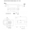
• The input cables from the mains/generator and the inverter, and output cables to the appliances should be connected according to the wiring diagram (see figure 1). Use the provided cable-glands to pass the cables through the casing. The correct wire cross section must be applied for a safe installation. Under sized cables can cause overheating of the cables.
• Tighten all connections well in order to limit transition resistance as far as possible. Loose connections can cause dangerous overheating of the terminals.
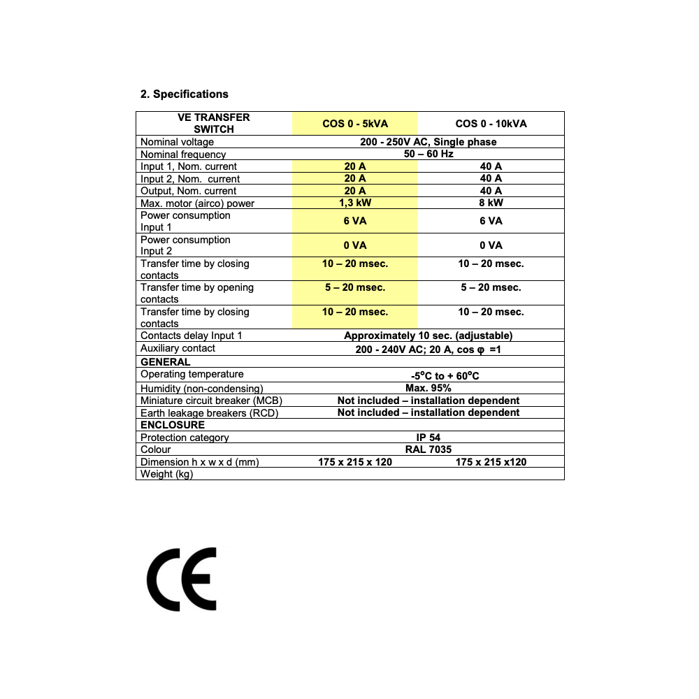
• Adjustment of the TRANSFER SWITCH is not recommended. After correct installation the TRANSFER SWITCH is ready for use. However specific circumstances may require adjustment of the switch on delay time of input 1. Use a small flat blade screw driver to adjust the delay time.
• The wiring to the AC-inputs and outputs must be protected by fuses or miniature circuit breakers which are suitable for the applied wire cross section. External earth leakage switches( RCD, RCCB) must also be integrated in the wiring
• All ground connections of the power sources and power consumers must be connected to the central ground connection of the ship.
• Auxiliary contact 1 and 2 of relay K2 (NO) must be connected with a screw connector on the back of Digital Multi Control panel (DMC) when an external transfer switch is used with VE MultiPlus and DMC (picture on page 7). When the auxiliary contact is open the current limit is controlled by the knob on the front of the DMC. When the auxiliary contact is closed the DMC sends the present generator current to connected devices. The auxiliary contact is normally controlled by the TRANSFER SWITCH.
10 other products in the same category:
Reviews (0)